The system uses compressed air and an industrial heat tube to produce the heat blast. The Dragon’s Breath – heat blaster hot air cannon stays hot with a constant low level of air flowing through it, until the Dragons Breath system is activated, and compressed air is blasted through the nozzle, thus blasting heat at the guests almost instantly. When the Dragon’s Breath is de-activated, the system almost instantly cuts off the heat the guests feel. The Dragon’s Breath system then goes into “ready” mode awaiting the next “go” signal.
Specification
Note: The specifications listed below are specific to our standard product. Pricing and specifications could vary depending upon customer’s needs.
Key Assumptions:
- Scenic elements needed to disguise the The Dragon’s Breath – heat blaster hot air cannon will be provided by others
- The overhead mounting locations are adequate for the hanging load
- There is adequate area around the The Dragon’s Breath – heat blaster for proper air flow
- The facility HVAC system will be able to handle the added heat load
- Compressed air will be provided at the necessary flow rate and pressure
Basic Equipment provided by Technifex:
- (1) High-heat tube with temperature control box and monitoring system
- (1) Compressed air accumulator tank
- (1) Solenoid valve to control high/low air flow
- (1) Coppus air accelerator
- (1) Hanging hardware
- (1) Over temperature cut-off switch
- (1) Fuse box
Goods and services furnished and installed by others:
- Compressed air supply and filtration, to Technifex specifications.
- Power stub-ups within 6 feet (2m) of Heat Blaster Cannon
- Show Control system to provide trigger signals
- Compressed air stub-up within 6 feet (2m) of Heat Blaster Cannon
- All scenic elements required as per art direction
- Hanging/Mounting points
Specifications: (approximate dimensions and weights)
- Heater/Controller Power: 240V System – (1) Circuit (208-240VAC, 3ph, 50/60 Hz, 40A)
- Heater/Controller Power: 480V System – (2) Circuits (480VAC, 3ph, 50/60Hz, 120A)
- Heater Intake Particle Filter: Mesh Size 22 x 22 / Opening Size 0.038″ (0.96mm) / Open Area 70% / Wire Dimeter 0.0075″ (0.19mm)
- Control: (2) Contact Closures (Input= Enable, Output= Fault), (2) 24VDC for air blast and air knife valves
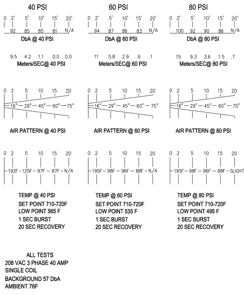
- Compressed Air (Avg.): 80 PSI @ 120 CFM (6.7 Bar @ 4247 lpm.)
- Compressed Air (Peak): 100 PSI @ 160 CFM (6.7 Bar @ 8495 lpm.)
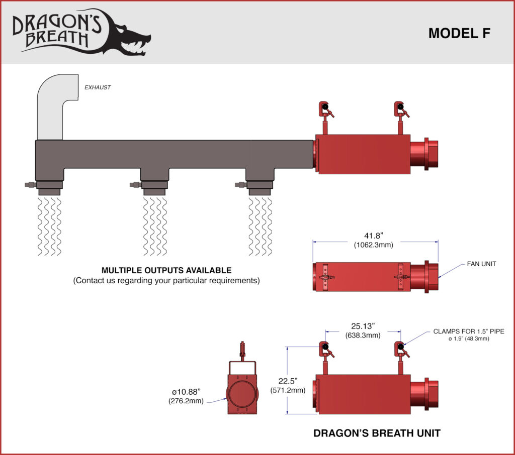
- Dimensions of Heat Blaster – FAN Version: 41.8″ x 22.5″ x 10.88″ (1062.3mm x 571.2mm x 276.2mm)
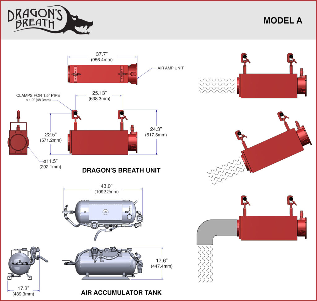
- Dimensions of Heat Blaster – AIR AMP Version: 37.7″ x 22.5″x 11.5″ (956.4mm x 571.2mm x 292.1mm)
- Dimensions of Air Accumulator Tank: 43″ x 17.6″ x 17.3″ (1092.2mm x 447.4mm x 439.3mm)
- Weight of Heat Blaster: 85 lbs. (38.5kgs)
- Weight of Air Accumulator Tank: 150 lbs. (68kgs)
Heater Control System
Heat Control System:
The Heat Controller utilizes a self-contained microprocessor based Process Controller. The unit monitors temperature utilizing a Type K thermocouple sensor and controls temperature with a rapid response three mode (PID) control scheme, with anti-reset windup. Numerous status and alarm functions are incorporated to monitor various system parameters.
The unit is housed in a NEMA 12 enclosure and contains the temperature controller and the necessary terminal blocks, transformers, safety relay and solid state relay to make up a complete system.
An independent high limit circuit is also provided. The sensor is a second Type K thermocouple. This circuit shuts off the internal safety relay should an over-temperature condition occur. It is totally independent of the microprocessor.
The following are some of the features:
- USES TYPE K THERMOCOUPLE FOR PROCESS CONTROL
- USES SECOND TYPE K THERMOCOUPLE FOR HIGH LIMIT
- AUTOMATIC THERMOCOUPLE COLD JUNCTION COMPENSATION
- HI LIMIT CIRCUITRY INDEPENDENT OF MICROPROCESSOR
- ADVANCED RAPID RESPONSE 3 MODE CONTROL
- BUILT IN SAFETY RELAY
- BUILT IN SOLID STATE RELAY
- BUILT IN CLASS 2 TRANSFORMER
- EXTERNAL HEAT SINK
- ON/OFF SWITCH
- HEATER SNAP SWITCH INPUT
- FLOW SWITCH INPUT
- ACCESS CODE PARAMETER PROTECTION
- EEPROM PARAMETER MEMORY
- AUDIO ALARM/ANNUNCIATOR
- ALL PARAMETERS SET IN SOFTWARE
- NEMA 12 ENCLOSURE
- TWO FOUR DIGIT LED DISPLAY
Blast Diagram